


Add Compatible Accessories

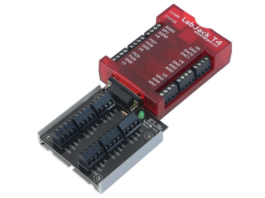
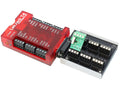
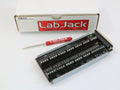
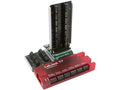
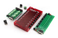
The CB15 provides convenient screw terminals for the 12 digital I/O lines on the DB15 connector of compatible LabJack devices. Includes a screwdriver. Not co...


In stock
CB15 Terminal Board
$33
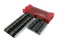
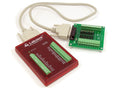
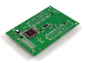
The CB15 provides convenient screw terminals for the 12 digital I/O lines on the DB15 connector of compatible LabJack devices. Includes a screwdriver. Not compatible with the U12.
Mounting Note: This accessory may ship in a gray plastic Snaptrack tray. Please note that this tray no longer supports the DIN rail clips. For DIN rail installations, use the included LJSnap2D adapters, which are fully compatible with TKAD clips.
For more information, see the CB15 Datasheet.
For more information, see
CB15 Terminal Board Datasheet.

The LJTick-InAmp 2, revision 2, (LJTick-InAmp 2) is EoL & NRND (End Of Life and Not Recommended for New Designs). It has been replaced by a newer, and s...


Out of stock
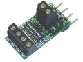
LJTick-InAmp 2 (LJTIA 2) - NRND, EoL
$90
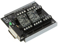
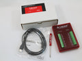
The LJTick-InAmp 2, revision 2, (LJTick-InAmp 2) is EoL & NRND (End Of Life and Not Recommended for New Designs). It has been replaced by a newer, and simpler, InAmp 3 (Rev 3).
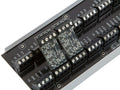
The LabJack Tick-InAmp 2 (LJTIA 2) signal-conditioning module provides two instrumentation amplifiers ideal for low-level signals such as bridge circuits (e.g. strain gauges) and thermocouples. Each amplifier converts a differential input to single-ended. The LJTIA 2 has switches to choose from 5 gain settings (x1, x11, x51, x201, or custom) and two output voltage offsets. The 4-pin design plugs into the standard AIN/AIN/GND/VS screw terminal block found on LabJacks such as the U3, U6, UE9, T4, and T7.
The LJTIA 2 datasheet has more information.
For more information, see
LJTick-InAmp 2 (LJTIA 2) - NRND, EoL Datasheet.

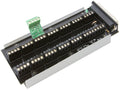
Provides convenient screw terminals for the DB37 connector on the LabJack U6, UE9, and T7. Includes a screwdriver. Compatible with LJTick signal-conditio...


In stock
CB37 Terminal Board
$58
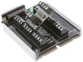
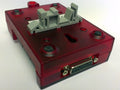
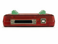
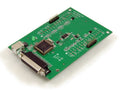
Provides convenient screw terminals for the DB37 connector on the LabJack U6, UE9, and T7. Includes a screwdriver. Compatible with LJTick signal-conditioning modules.
Mounting Note: This accessory may ship in a gray plastic Snaptrack tray. Please note that this tray no longer supports the DIN rail clips. For DIN rail installations, use the included LJSnap2D adapters, which are fully compatible with TKAD clips.
For more information, see the CB37 Terminal Board (Rev 2.1) Datasheet.
For more information, see
CB37 Terminal Board Datasheet.

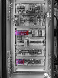
Clip used to mount a LabJack device to a DIN rail. Simply attach this clip to the backside of a LabJack device, and clip it to any DIN rail. This clip is man...


In stock
DIN Rail Mounting Clip
$6
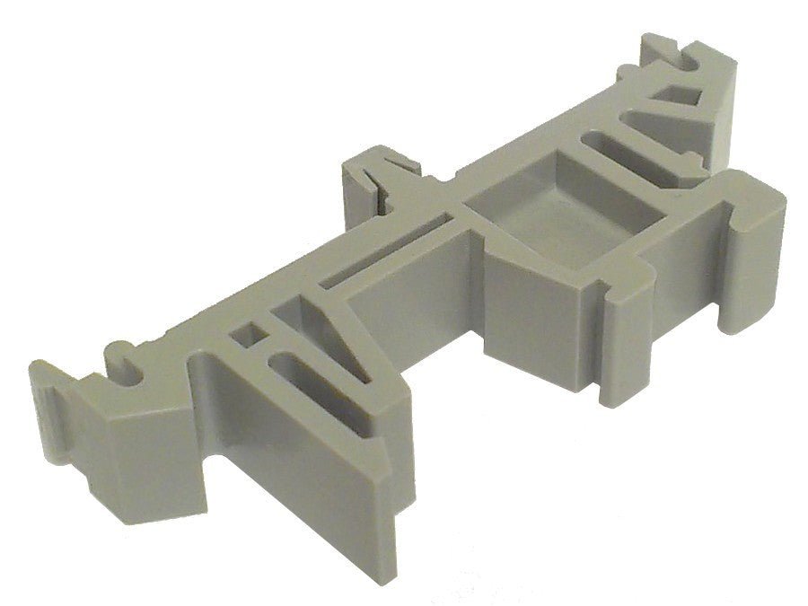
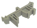
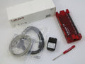
Clip used to mount a LabJack device to a DIN rail. Simply attach this clip to the backside of a LabJack device, and clip it to any DIN rail. This clip is manufactured by TE Connectivity, p/n TKAD, or 6-1437661-4.
We recommend two TKAD mounting clips per U6, UE9, T7, and T8, because these LabJack devices have mounting locations for two clips. As shown in the image, the U3 and T4 only has one spot for a clip.
Our DIN Rail clips will ship with a 3d printed mounting adapter that will allow you to mount our accessory boards to a DIN rail. They will take the place of the snaptrack, and will be able to snap directly to the PCB.
More details, including CAD drawings, are available from TE Connectivity.
For more information, see
DIN Rail Mounting Clip Datasheet.
The EI-1022 is NRND ( Not Recommended for New Designs ). See the compliance page for more details. Easy to use and inexpensive temperature probe from El...

In stock
EI1022 Temperature Probe
$40
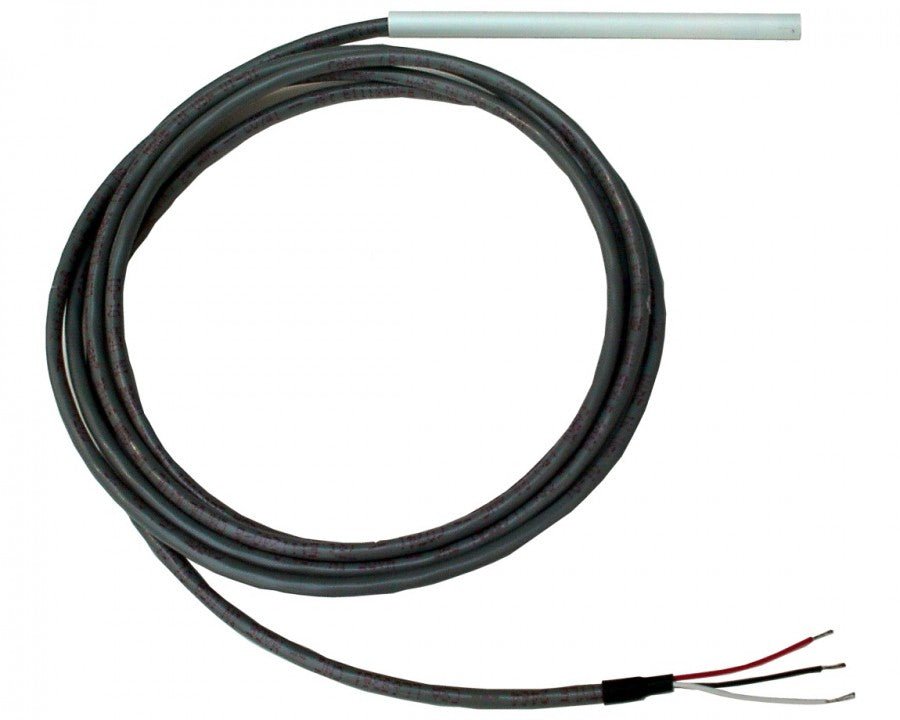
The EI-1022 is NRND ( Not Recommended for New Designs ). See the compliance page for more details.
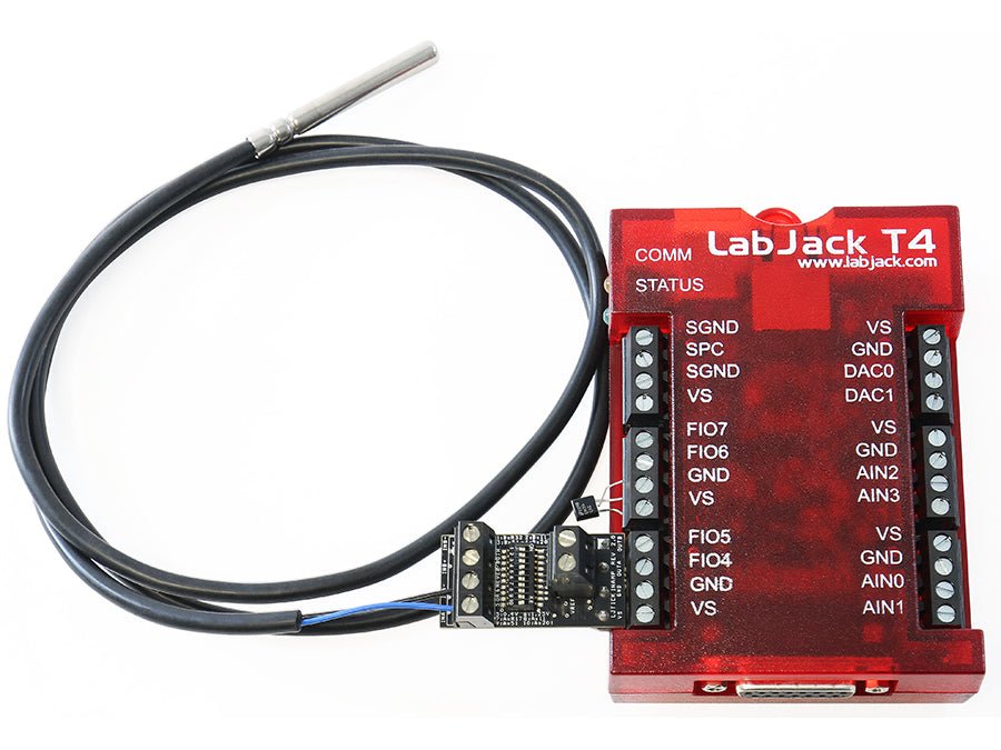
Easy to use and inexpensive temperature probe from Electronic Innovations Corp. Features a plastic probe, a high-level linear output of 10 mV per degree K, a typical accuracy of ±1 degrees C (±1.8 degrees F) at room temperature, and a range of -40 to +100 degrees C (-40 to +212 degrees F).
For more information, see the EI-1022 Datasheet.
For more information, see
EI1022 Temperature Probe Datasheet.
The EI-1034 is EoL ( End of Life ). See the compliance page for more details. Easy to use and very accurate temperature probe from Electronic Innovation...


Out of stock
EI1034 Temperature Probe - EoL
$70
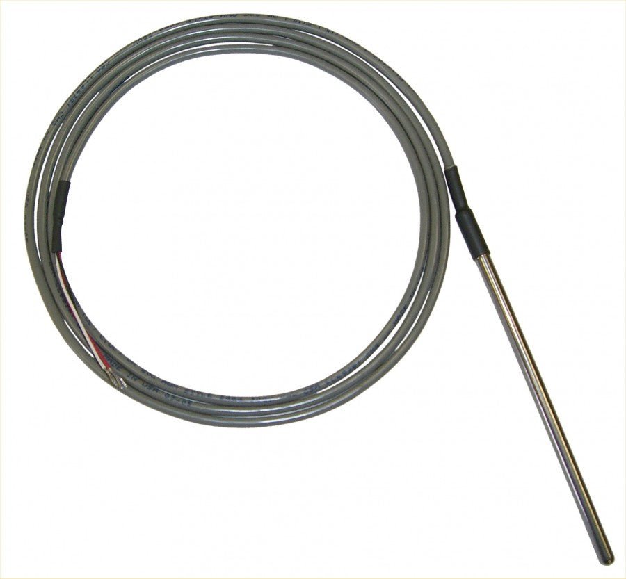
The EI-1034 is EoL ( End of Life ). See the compliance page for more details.
Easy to use and very accurate temperature probe from Electronic Innovations Corp. Features a waterproof stainless-steel probe, a high-level linear output of 10 mV per degree F, a typical accuracy of ±0.4 degrees F (±0.22 degrees C) at room temperature, and a range of 0 to +230 degrees F (-17 to +110 degrees C, with U3/UE9).
For more information, see the EI-1034 Datasheet.
For more information, see
EI1034 Temperature Probe - EoL Datasheet.

General purpose dual instrumentation amplifier. Often used in conjunction with the LabJack U12 to provide analog input gain. Operates from a single 5 volt su...


Out of stock
EI1040 Dual Instrumentation Amplifier
$180
General purpose dual instrumentation amplifier. Often used in conjunction with the LabJack U12 to provide analog input gain. Operates from a single 5 volt supply and provides a ±15 volt supply and a 4.096 volt reference voltage. Analog input range is ±10 volts. The gain of each channel is set to 1, 10, 100, or 1000 via digital I/O or jumper wires.
For more information, see the EI-1040 Dual Instrumentation Amplifier Datasheet.
End Of Life (EOL) Notice
Limited Availability: The EI-1040 dual instrumentation amplifier, manufactured by Electronic Innovations Corporation and sold by LabJack, is at the end of production. Estimated time of NLA (no longer available) is Spring 2023.
For more information, see
EI1040 Dual Instrumentation Amplifier Datasheet.

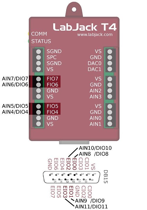
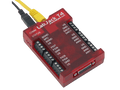
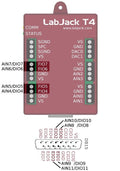
Analog Inputs (4): ±10V range and 12-bit resolution. Flex Lines (8): 0-2.5V analog input or 3.3V Digital IO. Digital IO (16): 8 dedicated Digital IO an...


In stock
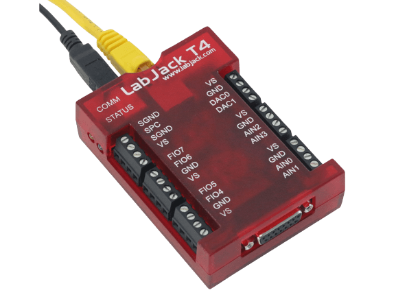
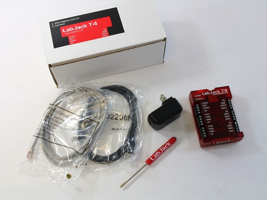
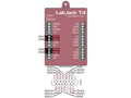
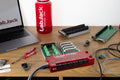
LabJack T4
$305
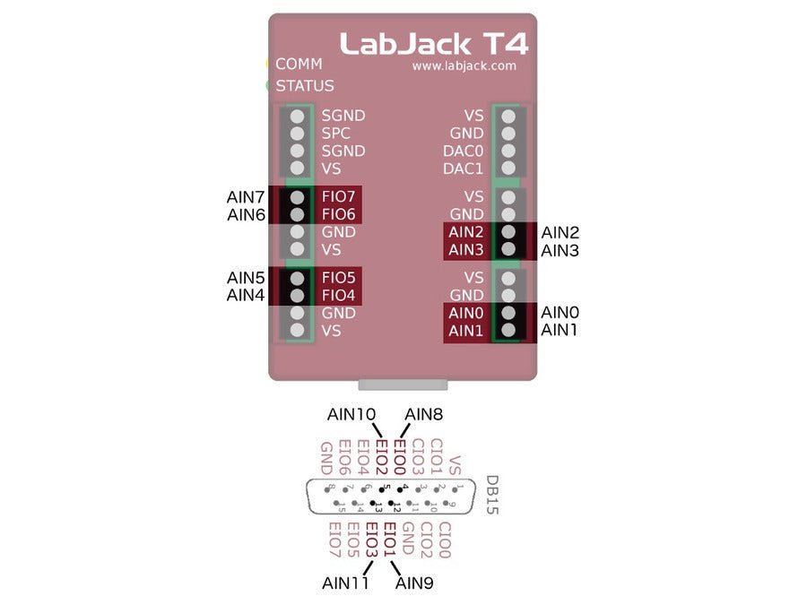
- Analog Inputs (4): ±10V range and 12-bit resolution.
- Flex Lines (8): 0-2.5V analog input or 3.3V Digital IO.
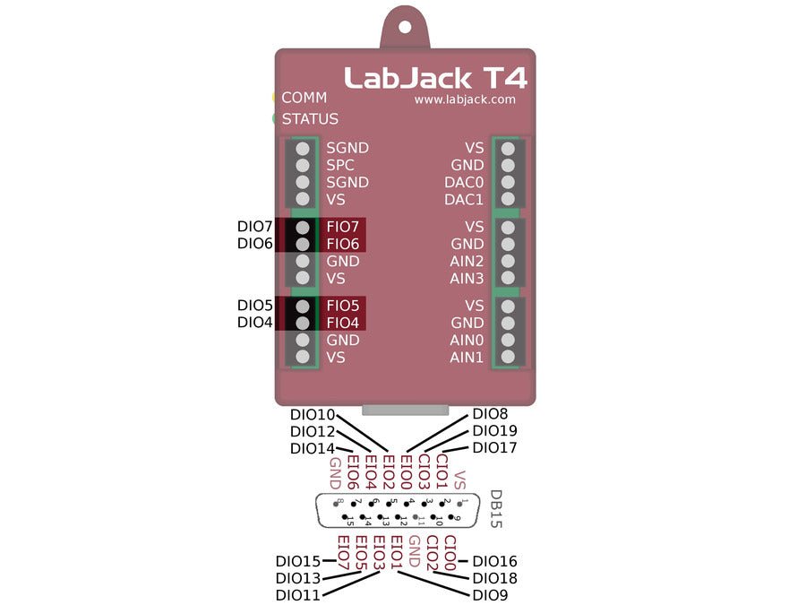
- Digital IO (16): 8 dedicated Digital IO and 8 Flex lines (above)
- Analog Outputs (2): 0-5V and 10-bit resolution
- Digital Features: Counters, PWM, frequency, I2C and more
- Sampling Rate: Up to 50k samples per second.
- USB & Ethernet: Controlled through USB or Ethernet.
- Onboard Scripting: Run Lua scripts right on the device.
- Easy to use API: Works with the LabJack Modbus (LJM) library.
For more information, see
LabJack T4 Datasheet.

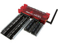
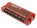
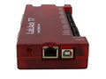
Choose the LabJack T7 for ultimate power and data acquisition flexibility. With 16-bit analog inputs, the option to use USB or Ethernet, and numerous built-i...


In stock
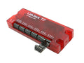
LabJack T7
$570
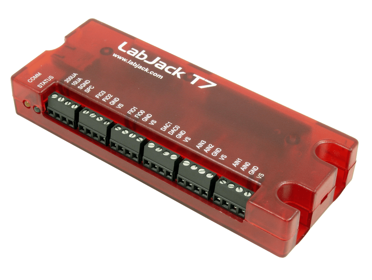
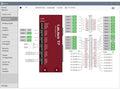
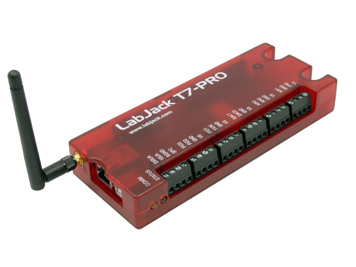
Choose the LabJack T7 for ultimate power and data acquisition flexibility. With 16-bit analog inputs, the option to use USB or Ethernet, and numerous built-in firmware features, the T7 can help you accomplish nearly any DAQ need. The LabJack T7 also has 2 analog outputs (12-bit), 23 digital I/O, and up to 10 digital counters/timers.
With 14 instrumentation amplified analog inputs, software selectable gain settings, dozens of digital I/O features, and a Modbus TCP front-end, the T7 is a versatile multifunction DAQ platform. Common applications include laboratory research, industrial control and monitoring, automated testing, and prototype development. Additionally, T7 devices are capable of stand-alone operation by running Lua scripts.
Consider the T7-Pro for applications requiring WiFi, a real time clock (RTC), or an auxiliary 24-bit low-speed ADC. For isolated, simultaneous or high speed, 24-bit measurements, consider the LabJack T8.
For more information, see
LabJack T7 Datasheet.

All the features of the normal T7 with the major addition of WiFi connectivity and an auxiliary low-speed high-resolution (24-bit) sigma-delta ADC. The T7-Pr...


In stock
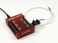
LabJack T7-Pro
$850
All the features of the normal T7 with the major addition of WiFi connectivity and an auxiliary low-speed high-resolution (24-bit) sigma-delta ADC. The T7-Pro also includes a real time clock (RTC) and 4GB MicroSD card for standalone datalogging.
With 14 instrumentation amplified analog inputs, software selectable gain settings, dozens of digital I/O features, and a Modbus TCP front-end, the T7 is our most versatile multifunction DAQ platform. Common applications include laboratory research, industrial control and monitoring, automated testing, and prototype development. Additionally, T7 devices are capable of stand-alone operation by running Lua scripts.
The LabJack T7 also has 2 analog outputs (12-bit), 23 digital I/O, and up to 10 digital counters/timers.
For more information, see
LabJack T7-Pro Datasheet.

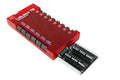
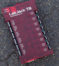
The LabJack T8 is the new flagship T-Series device adding powerful features including: 8x isolated analog inputs (AIN) with simultaneous sampling. ±1 kV AIN...


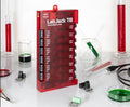


In stock
LabJack T8
$1,400
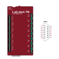
The LabJack T8 is the new flagship T-Series device adding powerful features including:
- 8x isolated analog inputs (AIN) with simultaneous sampling.
- ±1 kV AIN isolation channel-to-channel and channel-to-ground.
- Top performance for thermocouples, load cells, bridge circuits, and more.
- 8x 24-bit ΣΔ ADCs (up to 40k samples/s/ch).
- 10+ AIN voltage ranges: ±11V, to ±0.075V.
- 2 analog outputs (16-bit, 0-10V) with 20 mA drive.
- 20 digital I/O similar to the T7.
- Lua scripts are faster with 5x the code space than the T7.
- 3.3V fixed voltage outputs for excitation.
- Supported by LJM. LabJack's free, 3rd generation, cross-platform driver/library/API for simplifying device communication.
- Industrial temperature range (-40 to +85C).
- USB & Ethernet.
- Built-in Power over Ethernet (PoE), or power through USB connection.
For more information, see
LabJack T8 Datasheet.

USB DAQ device with 8 analog inputs(12-bit), 2 analog outputs(10-bit), 20 digital I/O, and a 32-bit counter. USB Multifunction DAQ The U12 is the origina...


In stock
LabJack U12
$240
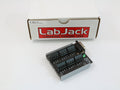
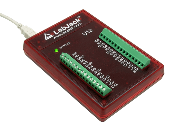
USB DAQ device with 8 analog inputs(12-bit), 2 analog outputs(10-bit), 20 digital I/O, and a 32-bit counter.
USB Multifunction DAQ
The U12 is the original LabJack. The device is solid - the firmware hasn't changed in a decade, and it has a very long service record of reliability and customer satisfaction - all with an attractive price point. It can be used for measurement and control within simple analog and digital systems.
We continue to produce the U12 to support our customers who have integrated it into existing designs. For all new applications, we recommend the T4 or any of our other T-Series devices. This newer family offers faster speeds, greater hardware flexibility, and is supported by our latest cross-platform LJM API.
For more information, see
LabJack U12 Datasheet.
Available
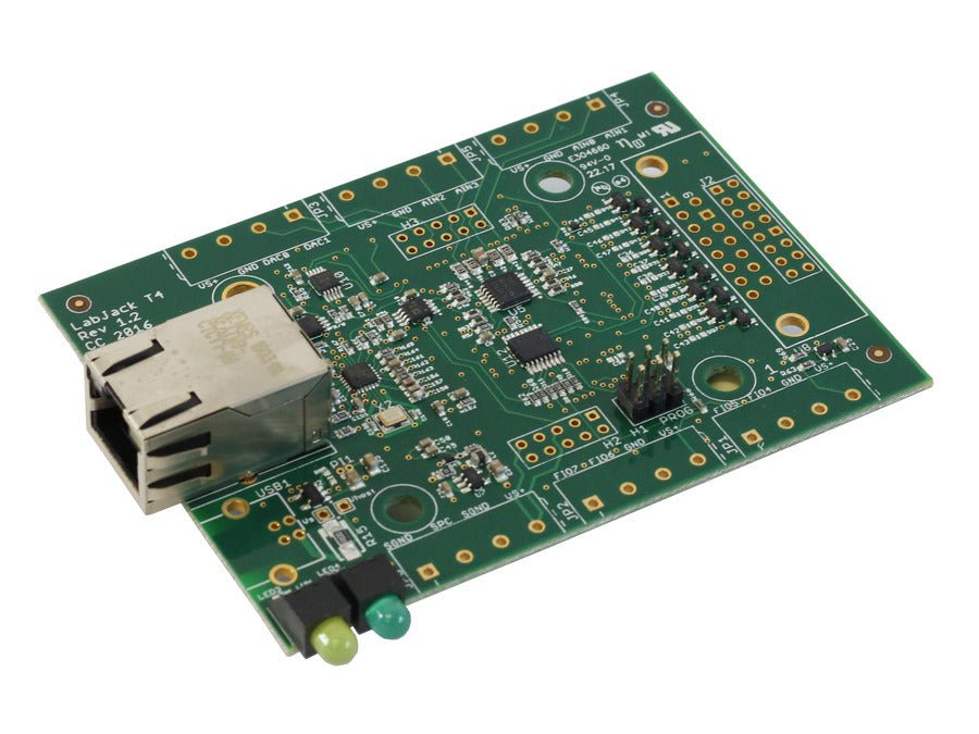
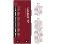
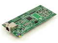
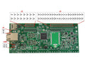
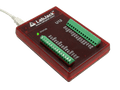
LabJack T4
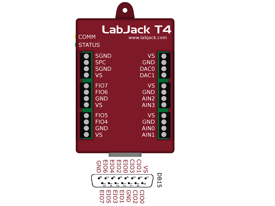
The T4 is a USB and Ethernet based multifunction DAQ device that provides 4 high-voltage analog inputs, 8 flexible I/O (FIO) for analog, digital or counter functions, 8 dedicated digital I/O, and 2 analog outputs. This is LabJack's most cost-effective USB based device—ideal for a wide range of applications.
Regular price
Price
Sale price
$305
Product Highlights

Unlimited Support
Free technical support

Money‑Back Guarantee
60‑day guarantee

Immediate Shipping
Ships same day
Volume Pricing
Pricing shown per unit and total order value
Quantity
Unit Price
Total Price
Savings
Savings %
10
00
00
Save $00
8%
30
00
00
Save $00
14%
100
00
00
Save $00
20%
Documentation & Details
Features
Technical Resources
FAQs
Why Choose LabJack?
Choose LabJack for reliability, flexibility, and unbeatable support—all backed by a 5-year warranty and lifetime assistance.

Flexibility & Integration
Versatile hardware with OEM variants for embedding into your own designs.

In stock
Our goal is to have every item in stock, all the time.

US Based
The LabJack HQ and staff are located in Colorado, USA.

Lifetime Support
Enjoy lifetime support provided by our US based team.

5-Year Warranty
LabJack offers a 5-year warranty for long-term protection.

