 |
LJM Modbus MapLJM Modbus Map - Use this tool to discover device features and while developing software to double check register types, names, and functionality. |
 |
Application NotesApplication Notes - In-depth detail on various DAQ topics. |
LabJack T7-Pro
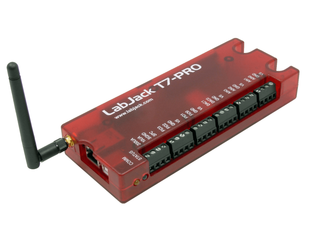
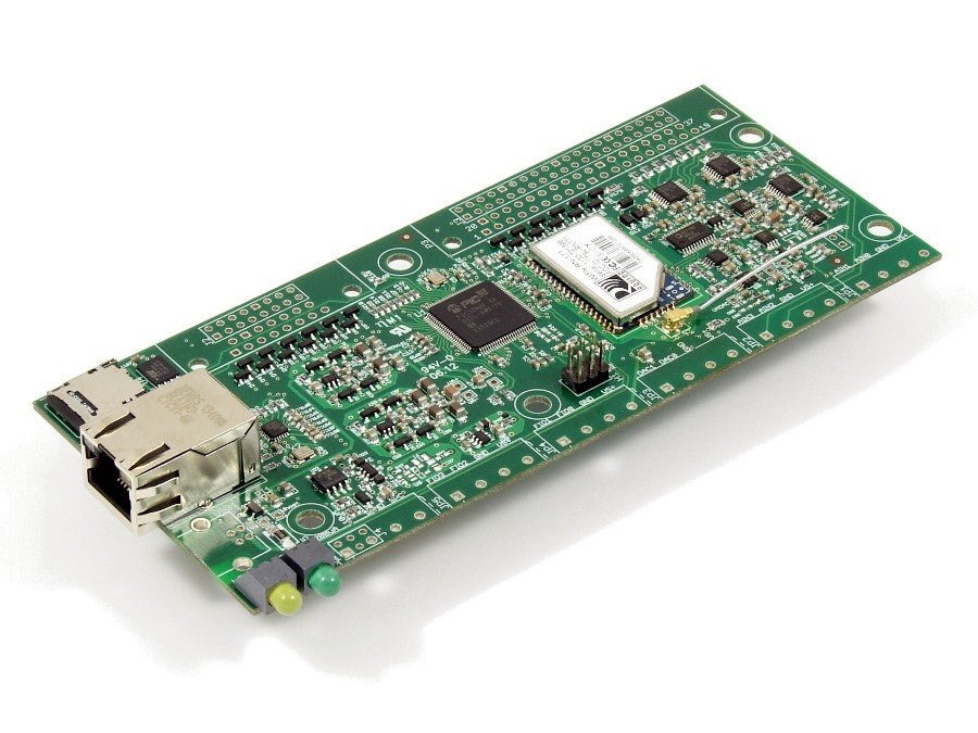
All the features of the normal T7 with the major addition of WiFi connectivity and an auxiliary low-speed high-resolution (24-bit) sigma-delta ADC. The T7-Pro also includes a real time clock (RTC) and 4GB MicroSD card for standalone datalogging.
With 14 instrumentation amplified analog inputs, software selectable gain settings, dozens of digital I/O features, and a Modbus TCP front-end, the T7 is our most versatile multifunction DAQ platform. Common applications include laboratory research, industrial control and monitoring, automated testing, and prototype development. Additionally, T7 devices are capable of stand-alone operation by running Lua scripts.
The LabJack T7 also has 2 analog outputs (12-bit), 23 digital I/O, and up to 10 digital counters/timers.
Stock status: In Stock
Stock status: In Stock
The only DAQ you will likely ever need!
With instrumentation amplified inputs, software selectable gain settings, dozens of digital I/O features, and a Modbus TCP front-end, the T7 is our most versatile multifunction DAQ platform.
Common applications include laboratory research, industrial control and monitoring, automated testing, and prototype development. Additionally, T7 devices are capable of stand-alone operation by running Lua scripts.

Product Specs
T7 Hardware Overview
Analog Input
- 14 Analog Inputs built in (16-24 Bits Depending on Speed & Device Type)
- Expand to 84 analog inputs with Mux80 add-on
- T7: 16-bit high-speed ADC (up to 100k samples/s)
- T7-Pro: 24-bit low-speed ADC (resolution as low as 1uV noise-free)
- Software Configurable Resolution Settings
- Single-Ended Inputs (14) or Differential Inputs (7)
- Analog input ranges: ±10V, ±1V, ±0.1V and ±0.01V
- All analog input features are software programmable by configuring the Analog Input Registers
- High speed sampling configurable by using Stream Mode. Speeds up to 100kS/s
- Low Latency Sampling and Control (less than 1ms) is made easy with Command-Response Modbus messages
- Easy integration with sensors like thermocouples, load cells, bridges, and more ...
Analog Output
- 2 analog outputs (12-bit, 0-5V)
- Waveform generation via Stream Out
- Integrated LJTick-DAC support for multiple +/-10V outputs
Digital I/O
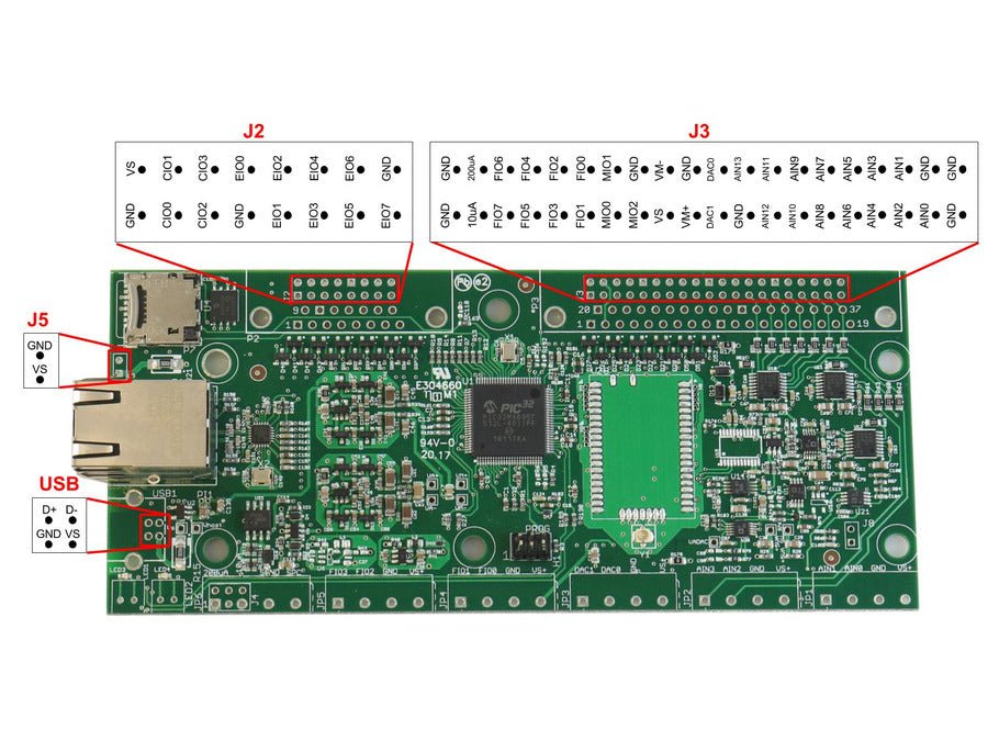
- 23 Digital I/O
- Supports SPI, I2C, and more... (Master Only)
- 5 PWM Outputs with individual phase control
- 5 Pulse Outputs with configurable number, frequency, and width
- 2 Frequency Inputs returning both frequency and period
- 2 Pulse Width Inputs measuring time spent high and low as well as duty cycle
- 2 Line-to-Line Inputs measuring the time between edges on 2 different lines
- 4 High-Speed Counters
- 6 Software Counters with debounce capabilities
- 3 Pairs of Quadrature Inputs
- Many of these DIO Extended Features share pins and cannot be used at the same time. See the DIO Extended Features section of the T7's datasheet
Fixed Current Outputs
- 200 µA
- 10 µA
Communication Options
- USB
- Ethernet
- 802.11b/g WiFi (T7-Pro only)
Other Highlights
- Capable of stand-alone operation by running Lua Scripts
- Built-In CJC Temperature Sensor for easy thermocouple temperature readings
- Watchdog system
- Field Upgradable Firmware
- Programmable Startup Defaults
- Industrial temperature range (-40 to +85C)
- For more information please visit the hardware overview section of the T7's datasheet
Further Reading
More technical specifications about the T7 can be found in Appendix A of the T7's Datasheet.
T7- Package Contents
Package Contents (Non-OEM)
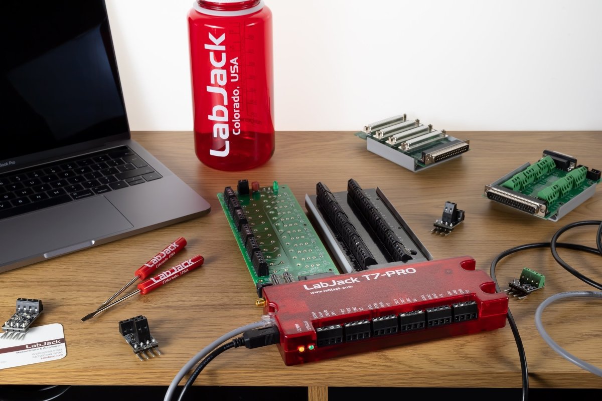
- T7 (-Pro) unit itself in red enclosure
- USB cable (6 ft / 1.8 m)
- Ethernet Cable (6ft / 1.8m)
- USB 5V power supply
- Screwdriver
- Antenna (T7-Pro only)
- Other package details: No software CD included. Download free software from labjack.com.
- Retail packing (Package) size: 10" x 7" x 3"
- Retail packing (Package) wt: 1.2lb

T7 vs. T7-Pro
What is the difference between the T7-Pro vs. T7?
The T7-Pro has the following additional features:- 802.11b/g WiFi connectivity. (antenna included)
- Low-Speed and High-Resolution (24-bit) sigma-delta ADC.
- Battery Backed RTC for stand-alone data logging.
- Factory Installed 4Gb+ microSD card for stand-alone data logging.
AIN Extended Features [T-Series Datasheet]
Analog Extended Features (AIN-EF) simplify some common analog input applications. Each AIN-EF feature:
- collects one or more input samples
- performs math on the collected samples
AIN-EF is only supported in command-response mode and not in stream mode.
Kipling Walkthrough: Kipling's Register Matrix can be used to perform AIN-EF features. For example:
Available AIN Extended Features
For any given AIN channel, one AIN-EF feature may be selected. AIN-EF indices:
| Index | AIN-EF Name | Supported Devices | Performs Stream Internally? |
| 0: | None (disabled) | All T-series | |
| 1: | Offset and Slope | All T-series | |
| 3: | Max, Min, Avg | All T-series | Yes |
| 4: | Resistance | All T-series | |
| 5: | Average and Threshold | All T-series | Yes |
| 10: | RMS Flex | All T-series | Yes |
| 11: | RMS Auto | All T-series | Yes |
| 20: | Thermocouple type E | T7 only | |
| 21: | Thermocouple type J | T7 only | |
| 22: | Thermocouple type K | T7 only | |
| 23: | Thermocouple type R | T7 only | |
| 24: | Thermocouple type T | T7 only | |
| 25: | Thermocouple type S | T7 only | |
| 30: | Thermocouple type C | T7 only | |
| 40: | RTD PT100 | All T-series | |
| 41: | RTD PT500 | All T-series | |
| 42: | RTD PT1000 | All T-series | |
| 50: | Thermistor using Steinhart-Hart equation | All T-series | |
| 51: | Thermistor using Beta equation | All T-series |
Support Resourses
LabJack Quickstart Tutorials
LabJack quickstart tutorials show new users how to measure a voltage, change a digital I/O, and set the voltage of an analog output using our free software. These tutorials teaches basic software and device functionality, and is also useful as a quick debugging check to verify that I/O on the device are working properly.
Bridge Circuits, Load Cells, Pressure Sensors and Strain Gauges
If you are using a raw bridge sensor/load cell/strain gauge that is ratiometric (mV/V) and are simply looking for guidance on which products to use, we suggest using a LabJack T7 and LJTick-VRef41 for the best measurements and ease of use.
For a detailed guide read the LabJack Bridge Circuit App Note
The Wheatstone bridge can be used to measure capacitance, inductance, impedance and other quantities.
Keywords: loadcell, strain gauge, strain gage, bridge circuits, potentiometer, raw bridge circuit, H-bridge, iepe, Integrated Electronics Piezo-Electric
Frequently Asked Support Questions
AIN (Analog Inputs)
A1. My analog input is stuck on some wrong value.
- See Suspicious Values.
A2. My analog input is returning varying values but not the right value.
A3. My readings are too noisy.
- See Too Much Noise.
A4. How do I measure temperature using a thermocouple, RTD, thermistor or other?
- Start on the Temperature Sensors App Note.
A5. My thermocouple readings are wrong.
- Determine if the error is from the cold junction sensor, the A/D conversion, or the signal itself.
- If the cold junction reading is off by a few degrees that error will show up in your calculated thermocouple temperature.
- Remove the thermocouple, and instead jumper the analog input (or both analog inputs for differential) to GND. The thermocouple voltage is now 0.0 volts which is saying both ends of the thermocouple are at the same temperature and thus the thermocouple temperature you calculate will be equal to the cold junction temperature.
- Remove the thermocouple from the system under test and instead just set it next to the LabJack so the thermocouple is measuring air temperature near the LabJack. If the terminals you are connecting to are at air temperature (e.g. CB37 terminals), the expected voltage is 0.0 volts. If the terminals you are connecting to are warmer than air temperature (e.g. T7 terminals), the expected voltage is a negative value dependent on the temperature difference.
- See Thermocouple Complications.
- See Thermocouple Troubleshooting Tips.
A6. I need to monitor a 4-20 mA current loop signal or measure some other current.
- LabJack analog inputs measure voltage. The LJTick-CurrentShunt is an easy way to convert 4-20 mA to voltage. See the Measuring Current App Note.
A7. Should I use differential?
- Sometimes it is required or a good idea. See Why use Differential.
A8. Problem with differential analog inputs.
- The signals cannot be totally floating. See Differential inputs must have a reference.
- See Differential Test.
A9. How do I read from a load cell?
- Most load cells are raw bridge circuits. See the Bridge Circuits App Note.
A10. How do I measure pressure?
- See the Pressure Sensors App Note.
A11. Can I measure AC or DC?
- Yes, both. When you ask for 1 sample from the LabJack you get the voltage at that moment. If the signal is DC, you expect multiple samples over time to return the same value. If the signal is AC, the samples are taken at different points of the waveform and thus will return different values.
- If you want to acquire the waveform for an AC signal, you simply acquire multiple samples over time, which is often done using stream mode. Then if wanted you can do math on the waveform to determine parameters such as max/min, RMS, or frequency.
- On T-series devices you can use the AIN-EF system to acquire multiple samples over time, do some math, and return various values that describe the multiple samples (RMS, Peak-to-Peak, Period, Average, Max/Min).
- See the Measuring 120/240 VAC App Note.
A12. What is the max data rate?
- We have lots of detail for sample rates. U12, U3, U6, UE9, T-Series.
- For stream mode we usually specify the max sample rate. For max scan rate divide the max sample rate by number of channels. SampleRate = ScanRate * NumChannels.
- Extended channels on the Mux80 act just like normal channels. The max sample rate of the LabJack is still the same, you just use a bigger number for NumChannels in the above equation.
T7 Datasheet and Application Notes
Visit the Support page for additional information.
T7 Software Options
 |
Graphical applications for device configuration or basic data collection: LabJack applications. Programming for custom behavior: the C/C++ LJM library or any LJM language wrapper. |
For the full list, see this list of T7 Software Options.
T-Series Product Discovery Video
Can LabJack be used for Industrial Applications?
LabJack Devices:
- Can comfortably operate within the industrial temperature range (-40°C to 85C)
- Are capable of being mounted via DIN Rail/Snap track
- Integrate with Voltage Dividers for 24+ Volt signals
- NEMA 3 (or greater) enclosures recommended for any outdoor or indoor applications with dust, debris or in condensing humidity environments
- All LabJack products are covered by our industry leading 5 year warranty
- Have OEM Versions available for custom and embedded applications.
- Drawings and CAD Models Provided
- LabJack products are very robust, but subject to the influence of user connections.
- LabJack is not liable for any losses, expenses or damages beyond the LabJack device itself. See our Limitation of Liability for more details.

Optional Accessories:
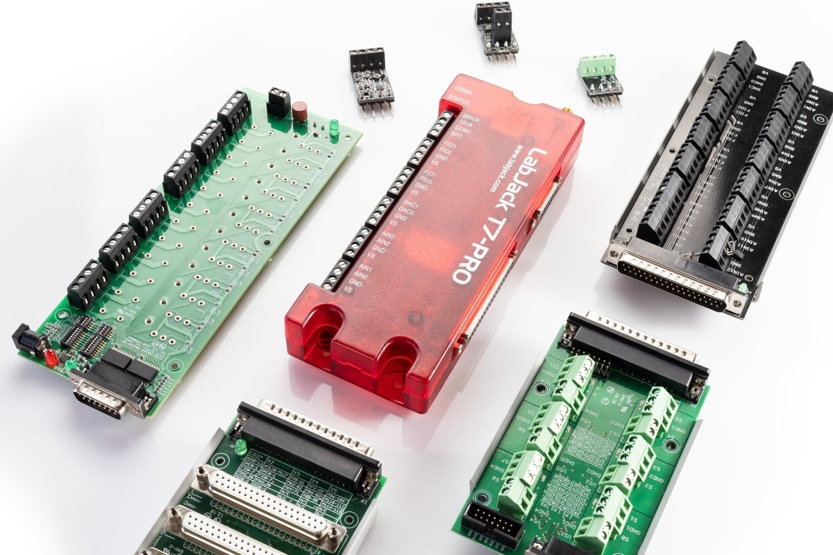
The CB15 is a simple screw terminal breakout for the DB15 connector.
The CB37 is a simple screw terminal breakout board for the DB37 connector. It only works with the U6 and T7 devices and can also be paired with the Mux80 for high channel application up to 84 AINs.
The Mux80 is an Analog Input Expansion board for the T7 and U6. Connected directly to the DB37 connector is can allow a single device to read up to 84 AINs.
The RB12 Relay Board provides a convenient interface for the LabJack to industry standard relays to interface a LabJack with high voltages/currents. The RB12 relay board connects to the DB15 connector on the LabJack. Output or input
The LJTick-Divider (LJTD) signal-conditioning module is designed to divide 2 single-ended higher voltage analog signals down to 0-2.5 volt signals.
The LJTick-DAC (LJTDAC) provides a pair of 14-bit analog outputs with a range of ±10 volts. Plugs into any digital I/O block, and thus up to 10 of these can be used per device to add 20 analog outputs.
The LJTick-InAmp (LJTIA) signal-conditioning module provides two instrumentation amplifiers ideal for low-level signals such as bridge circuits (e.g. strain gauges) and thermocouples. Each amplifier converts a differential input to single-ended.
The LJTick-RelayDriver (LJTRD) allows 2 digital I/O lines to each control a relay or other moderate load up to 50V/200mA.
The LJTick-CurrentShunt (LJTCS) signal-conditioning module is designed to convert a 4-20 mA current loop input signal into a 0.47-2.36 volt signal.
The LJTick-Proto (LJTP) consists of an 8x8 grid of holes for prototyping custom signal-conditioning modules.
What Type of Sensors Can I Connect to LabJack?
LabJack hardware can be connected to nearly any analog or digital sensor. Of course some sensors are easier than others to connect. If you haven't yet purchased your sensors please check out our App Notes for detailed guides and best practices. Generally the best sensors output an analog voltage in the 0-10v DC range. We have many signal conditioning modules we refer to as "Ticks" that make it easy to accept other signals and ranges
- LJTick-Current Shunt for 4-20mA signals
- LJTick-Divider for voltages over 10v
- LJTick-Vref for sensors that require a stable excitation/power source
- LJTick-Resistance for RTDs, Thermistors or resistive sensors
- LJTikc-InAmp for amplifying tiny signals like bridge circuits or thermocouples
Software & Drivers
Recommended Software
Though LabJack devices can be used with a variety of software options, we recommend the following—unless you already know what software you'd like to use.
If you'd like a graphical application for device configuration or basic data collection, see the available LabJack applications.
If you'd like to write a program for custom behavior, LabJack recommends the following:
T-Series (T4, T7, T7-Pro, T8)
Windows, Linux, and macOS: LJM library (C/C++) or any LJM language wrapper.
For the full list, see the T-series software options.
What is LJM?
LJM Library

LJM is LabJack's free, cross-platform driver / library for simplifying device communication. It supports the LabJack T4 and T7 series and T8 devices.
Download
See the LJM installer page to download.
Documentation
See the LJM User's Guide.
Features
- Cross-platform
- Supported in multiple languages
- Completely free
- Licensed with the permissive MIT X11 License
- Well-documented User's Guide
- Device discovery
- Device reconnection—automatically repairs connections
- Modbus Name-To-Address interpretation - ability to interpret LabJack register names such as "AIN0"
- Error-To-String Interpretation
-
Utility functions to:
- Convert bytes to values
- Perform thermocouple calculations
- Convert IP and MAC numbers
- Versatile Library configurations
- Threaded data streaming and buffering
- Thread-safe
- Basic demo mode for testing without a physical device.
Cross-Platform
Support for Windows, macOS, and Linux allows for the same code to be run on different operating systems with the same results, whether it's on your Windows desktop, MacBook laptop, or Raspberry Pi running a distribution of Linux.
Supported In Multiple Languages
Written in C++ with a C API, LabJack maintains and supports wrappers for many programing languages.
Some other supported languages:
- LabVIEW
- Visual Basic .NET
- DAQFactory
- See the full list of supported languages.
LJM's API allows for easy integration into most languages. If the language you use isn't currently supported, feel free to contact us for assistance in integrating LJM into your project.
LJM Is For Any Level Of Expertise
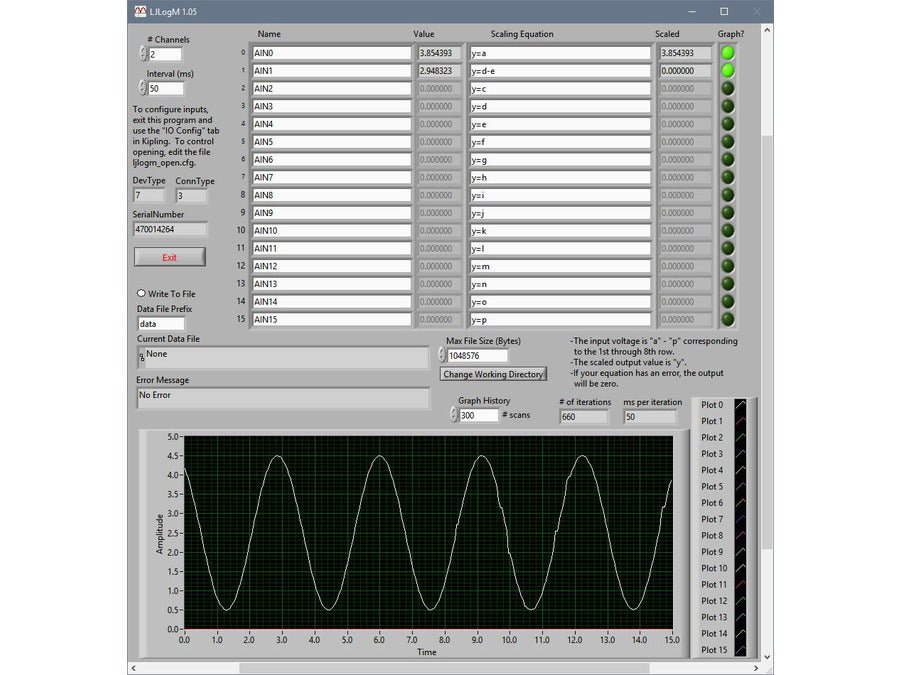
You don't need to be familiar with Modbus to use LJM. Simply use LJM's Easy Functions for direct access to all the features your LabJack device provides.
If you do prefer to use Modbus, LJM's Raw Byte Functions provide byte-level control to manually send and receive Modbus packets.
T7 Device FAQs
What does 12- or 16-bit resolution mean?
What is resolution?
Resolution in this context refers to the conversion of an analog voltage to a digital value in a computer (and vice versa). A computer is a digital machine and thus stores a number as a series of ones and zeroes. If you are storing a digital 2-bit number you can store 4 different values: 00, 01, 10, or 11. Now, say you have a device which converts an analog voltage between 0 and 10 volts into a 2-bit digital value for storage in a computer. This device will give digital values as follows:
| Voltage | 2-Bit Digital Representation |
|
0 to 2.5 |
00 |
So in this example, the 2-bit digital value can represent 4 different numbers, and the voltage input range of 0 to 10 volts is divided into 4 pieces giving a voltage resolution of 2.5 volts per bit. A 3-bit digital value can represent 8 (23) different numbers. A 12-bit digital value can represent 4096 (212) different numbers. A 16-bit digital value can represent 65536 (216) different numbers. It might occur to you at this point that a digital input could be thought of as a 1-bit analog to digital converter. Low voltages give a 0 and high voltages give a 1.
In the case of the LabJack U12, a single-ended analog input has a voltage range of -10 volts to +10 volts (20 volt total span) and returns a 12-bit value. This gives a voltage resolution of 20/4096 or 0.00488 volts per bit (4.88 mV/bit).
Compare In-Stock 12, 16 and 24 Bit LabJack Devices
Compare Now
What does it mean to say a device is 12-bit, 16-bit, or 24-bit?
When you see analog input DAQ devices from various manufacturers called 12-bit, 16-bit, or 24-bit, it generally just means they have an ADC (analog to digital converter) that returns that many bits. When an ADC chip returns 16 bits, it is probably better than a 12-bit converter, but not always. The simple fact that a converter returns 16-bits says little about the quality of those bits.
It is hard to simply state "the resolution" of a given device. What we like to do, is provide actual measured data that tells you the resolution of a device including typical inherent noise.
If you look at a device called "24-bit" just because it has a converter that returns 24-bits of data per sample, you will find that it typically provides 20 bits effective or 18 bits error-free (like the UE9-Pro). The U6-Pro and T7-Pro provide some of the best performance around from a 24-bit ADC, and they do about 22 bits effective or 20 bits error-free. You will see with these devices we might mention they have a 24-bit ADC (as that is what people look and search for), but we try not to call them "24-bit" and try to stick with the effective resolution.
Another interesting thing about your typical 24-bit sigma-delta converter, is that you can look at them as only having a 1-bit ADC inside, but with timing and math they can produce 24-bit readings:
https://www.maximintegrated.com/en/design/technical-documents/tutorials/1/1870.html
Additional device-specific resolution information can be found in the respective device datasheet:
LabJack Quickstart Tutorials
LabJack quickstart tutorials show new users how to measure a voltage, change a digital I/O, and set the voltage of an analog output using our free software. These tutorials teaches basic software and device functionality, and is also useful as a quick debugging check to verify that I/O on the device are working properly.
T7- Package Contents
Package Contents (Non-OEM)
- T7 (-Pro) unit itself in red enclosure
- USB cable (6 ft / 1.8 m)
- Ethernet Cable (6ft / 1.8m)
- USB 5V power supply
- Screwdriver
- Antenna (T7-Pro only)
- Other package details: No software CD included. Download free software from labjack.com.
- Retail packing (Package) size: 10" x 7" x 3"
- Retail packing (Package) wt: 1.2lb

T7 vs. T7-Pro
What is the difference between the T7-Pro vs. T7?
The T7-Pro has the following additional features:- 802.11b/g WiFi connectivity. (antenna included)
- Low-Speed and High-Resolution (24-bit) sigma-delta ADC.
- Battery Backed RTC for stand-alone data logging.
- Factory Installed 4Gb+ microSD card for stand-alone data logging.
Can LabJack be used for Industrial Applications?
LabJack Devices:
- Can comfortably operate within the industrial temperature range (-40°C to 85C)
- Are capable of being mounted via DIN Rail/Snap track
- Integrate with Voltage Dividers for 24+ Volt signals
- NEMA 3 (or greater) enclosures recommended for any outdoor or indoor applications with dust, debris or in condensing humidity environments
- All LabJack products are covered by our industry leading 5 year warranty
- Have OEM Versions available for custom and embedded applications.
- Drawings and CAD Models Provided
- LabJack products are very robust, but subject to the influence of user connections.
- LabJack is not liable for any losses, expenses or damages beyond the LabJack device itself. See our Limitation of Liability for more details.

What is LJM?
LJM Library

LJM is LabJack's free, cross-platform driver / library for simplifying device communication. It supports the LabJack T4 and T7 series and T8 devices.
Download
See the LJM installer page to download.
Documentation
See the LJM User's Guide.
Features
- Cross-platform
- Supported in multiple languages
- Completely free
- Licensed with the permissive MIT X11 License
- Well-documented User's Guide
- Device discovery
- Device reconnection—automatically repairs connections
- Modbus Name-To-Address interpretation - ability to interpret LabJack register names such as "AIN0"
- Error-To-String Interpretation
-
Utility functions to:
- Convert bytes to values
- Perform thermocouple calculations
- Convert IP and MAC numbers
- Versatile Library configurations
- Threaded data streaming and buffering
- Thread-safe
- Basic demo mode for testing without a physical device.
Cross-Platform
Support for Windows, macOS, and Linux allows for the same code to be run on different operating systems with the same results, whether it's on your Windows desktop, MacBook laptop, or Raspberry Pi running a distribution of Linux.
Supported In Multiple Languages
Written in C++ with a C API, LabJack maintains and supports wrappers for many programing languages.
Some other supported languages:
- LabVIEW
- Visual Basic .NET
- DAQFactory
- See the full list of supported languages.
LJM's API allows for easy integration into most languages. If the language you use isn't currently supported, feel free to contact us for assistance in integrating LJM into your project.
LJM Is For Any Level Of Expertise
You don't need to be familiar with Modbus to use LJM. Simply use LJM's Easy Functions for direct access to all the features your LabJack device provides.
If you do prefer to use Modbus, LJM's Raw Byte Functions provide byte-level control to manually send and receive Modbus packets.
DAQ Definition: What Is A DAQ System?
DAQ is short for data acquisition which is short for data acquisition and control. The term describes the process of acquiring readings from sensors and transducers (temperature, pressure, strain, etc.), and controlling actuators (relays, solenoids, etc.). In our case the emphasis is on computer-based DAQ, where the LabJack is the interface that allows a computer to read from sensors and control actuators.
T7-Pro Craftsmanship
High performance USB or Ethernet Multifunction Data Acquisition Module

Connect Quickly via USB, Ethernet or WiFi
USB or Ethernet multifunction DAQ device with 14 analog inputs (16- to 18- bit), 2 analog outputs (12-bit), 23 digital I/O, and up to 10 digital counters/timers.
Explore more14 Analog Inputs
Analog input ranges: ±10V, ±1V, ±0.1V and ±0.01V 16-bit high-speed ADC (up to 100k samples/s)
Explore moreConnect Almost Any Sensor
Easy integration with sensors like thermocouples, load cells, bridges, and many more. Detailed App-Notes to help get you started
Explore moreOther Highlights
Capable of stand-alone operation by running Lua Scripts. Built-In CJC Temperature Sensor for easy thermocouple temperature readings. Watchdog system. Field Upgradable Firmware. Programmable Startup Defaults. Industrial temperature range (-40 to +85C)
Explore morePowerful Digital I/O Capabilities
23 Digital I/O, Supporting SPI, I2C & More, PWM Outputs, Frequency Inputs, Counters, Timers and many more Extended Features
Explore moreEasily Expandable
High Channel Count? Expand up to 84 Analog Inputs with affordable accessories
Explore more
