
 |
Application NotesApplication Notes - In-depth detail on various DAQ topics. |
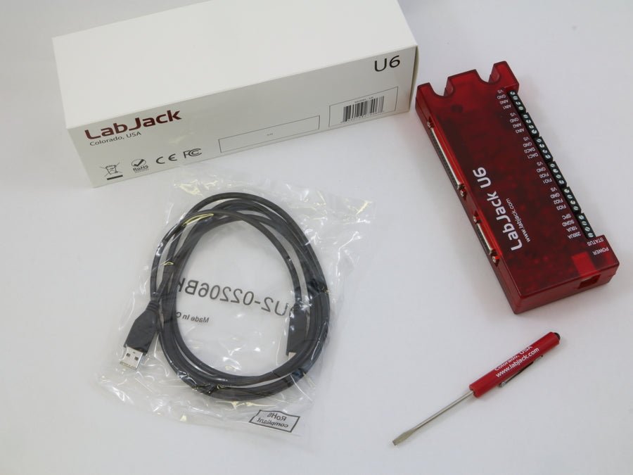


LabJack U6
Precision USB Multifunction DAQ
The LabJack U6 is great for acquiring signals from thermocouples, strain gages, bridge circuits, encoders, and nearly any sensor that outputs a voltage or current.
With instrumentation amplified analog inputs, and software selectable gain settings, the U6 provides a cost effective, USB only method to measure analog signals which can't be resolved by traditional 12-bit DAQ products. Common applications include laboratory research, industrial control and monitoring, and prototype development.
- 14 Analog Inputs (16-18-bit) expandable up to 84 AINs using Mux80 Expansion board
- ±10V, ±1V, ±0.1V and ±0.01V Voltage ranges
- 20 Digital I/O lines, 2 counters, and 4 timers
- 2 analog outputs (expandable using LJTick-DAC)
- Directly connect thermocouples, load cells, RTDs, and more …
- Industrial temperature range (-40 to 85°C)
- Free applications to configure, test, and log data to file
- Free examples: C/C++, C#, Python, Java, LabVIEW, MATLAB, VB.NET and more...
Consider the U6-Pro for applications requiring more than 16-bit analog inputs.
Regular price
Sale price
$445
Stock status: In Stock
Stock status: In Stock
Multifunction DAQ with DB15 and DB37 Connectors
The U6 family is great for acquiring signals from thermocouples, strain gages, bridge circuits, encoders, and much more. With instrumentation amplified inputs, and software selectable gain settings, the U6 provides a cost effective method to measure analog signals which can't be resolved by traditional 12-bit DAQ products. Common applications include laboratory research, industrial control and monitoring, and prototype development.

Product Specs
U6 Product Variations
U6 vs U6-Pro
The U6-Pro has the following additional features:
- Low-Speed and High-Resolution (24-bit) sigma-delta ADC giving access to resolution indices 9 through 12.
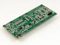
OEM Versions
The U6 and U6-Pro come in standard and OEM versions. The OEM versions are intended to be embedded in another device. They are missing the enclosure and most connectors, as it is easier to install connectors than it is to remove them. LabJack can customize the boards to add or remove hardware before shipping for an additional fee. More information on OEM versions can be found in the OEM versions section of the U6 datasheet.
U6 Product Highlights
Analog Inputs:
The LabJack U6 has 14 external analog inputs (AIN0-AIN13). AIN0-AIN3 are available on screw terminals and also on the DB37 connector. All 14 analog inputs are available on the DB37 connector.
The maximum input range is ±10 volts, with software selectable gains of x1, x10, and x100. Each analog input can be measured single-ended, or differentially in even/odd pairs. Analog input resolution is 16 bits at max speed (~20 μs conversion time), increasing to 18+ bits at slower speeds (see Section 3.1 - Command/Response and Section 3.2 - Stream Mode). Input impedance is at least 1 GΩ, with typical input bias currents of only 20 nA.
Command/response (software timed) analog input reads typically take 1-4 ms depending on number of channels and communication configuration. Hardware timed input streaming (supported with hi-speed converter only) has a maximum rate that varies with resolution from 4 ksamples/s at 18 bits to 50 ksamples/s at 16 bits.
For more information see the U6 Datasheet. The U6-Pro has all the features of the normal U6 with the addition of an auxiliary low-speed high-resolution (24-bit) sigma-delta ADC. Analog input resolution varies from 19.5 bits (RMS or Effective) at max speed (4 ms conversion time), to 22 bits at slower speeds (160 ms conversion time).
For more information about the analog inputs see Section 2.6 - AIN and Appendix A. For data rate information see Section 3.1 - Command/Response and Section 3.2 - Stream Mode.
Temperature Sensor:
The LabJack U6 has a temperature sensor located very close to the AIN0-AIN3 screw-terminals. Accuracy is ±2 degrees C (max). This sensor is particularly useful for thermocouple cold junction compensation (CJC).
Fixed Current Outputs:
The LabJack U6 has 2 fixed current outputs of 10 μA and 200 μA. These are useful for measuring resistance (resistors, thermistors, RTDs).
Analog Outputs:
The LabJack U6 has 2 analog outputs (DAC0 and DAC1) that are available both on screw terminals and the DB37 connector. Each analog output can be set to a voltage between about 0 and 5 volts with 12-bits of resolution. The analog outputs are based on a true voltage reference.
The analog outputs are updated in command/response mode, with a typical update time of 1-4 ms depending on communication configuration.
For more information see the U6 Datasheet. For more information about the analog outputs see Section 2.7 - DAC and Appendix A. For data rate information see Section 3.1 - Command/Response.
Digital I/O:
The LabJack U6 has 20 digital I/O channels which can be individually configured as input, output-high, or output-low.
The first 4 FIO are available on screw terminals and the DB37 connector. All 8 FIO and 3 MIO are available on the DB37 connector, and 8 EIO and 4 CIO are available on the DB15 connector. Note that on the U6, CIO0-CIO2 are the same as MIO0-MIO2.
Command/response (software timed) reads/writes typically take 1-4 ms depending on communication configuration. The digital inputs can also be read in a hardware timed input stream where up to 16 inputs count as a single stream channel.
For more information see the U6 Datasheet. For more information about the digital I/O see Section 2.8 - Digital I/O and Appendix A. For data rate information see Section 3.1 - Command/Response and Section 3.2 - Stream Mode.
Timers:
Up to 4 digital I/O can be configured as timers. The timers are very flexible, providing options such as PWM output, pulse timing, pulse counting, and quadrature input.
For more information about the timers see Section 2.9 - Timers/Counters and Appendix A of the U6 Datasheet.
Counters:
Up to 2 digital I/O can be configured as 32-bit counters. Since counting is one possible mode of the timers above, the U6 has up to 6 counting inputs.
For more information about the counters see Section 2.9 - Timers/Counters and Appendix A of the U6 Datasheet.
I/O Protection:
All I/O lines on the U6 are protected against minor overvoltages. The AIN lines can withstand continuous overvoltage of ±20 volts, the FIO lines can withstand up to ±10 volts, while the EIO/CIO/MIO lines can withstand up to ±6 volts.
High Channel Count Applications:
By using USB hubs, many LabJacks can be interfaced to a single PC, providing an inexpensive solution for high channel count applications.
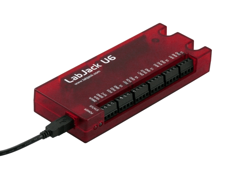
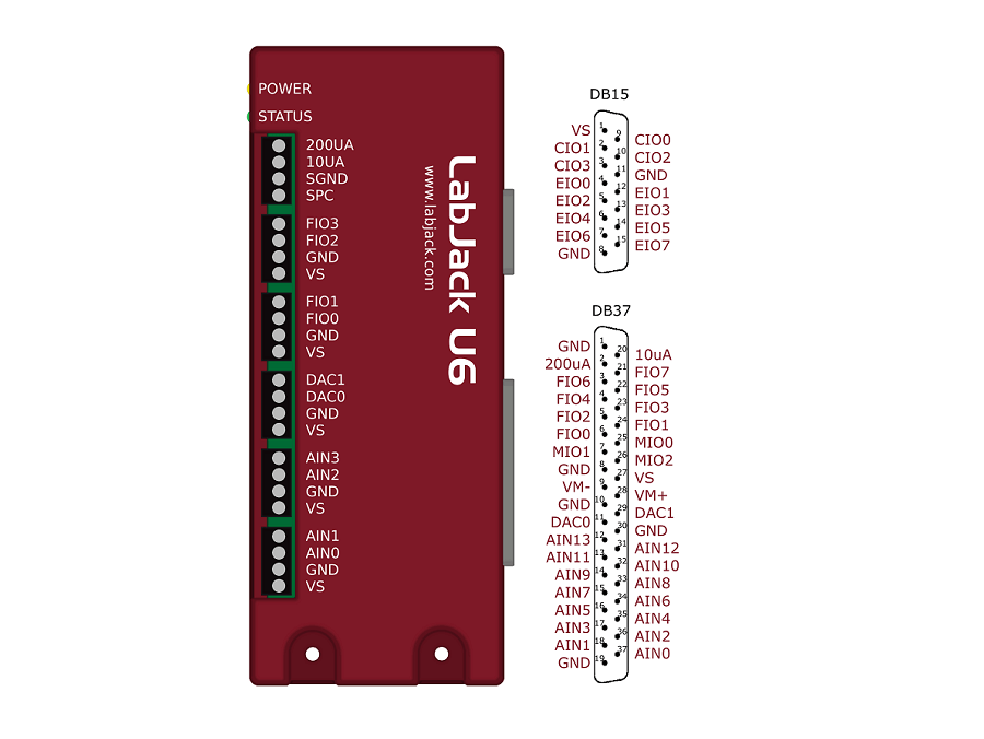
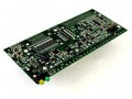
U6 Hardware Overview
The U6 has 3 different I/O areas:
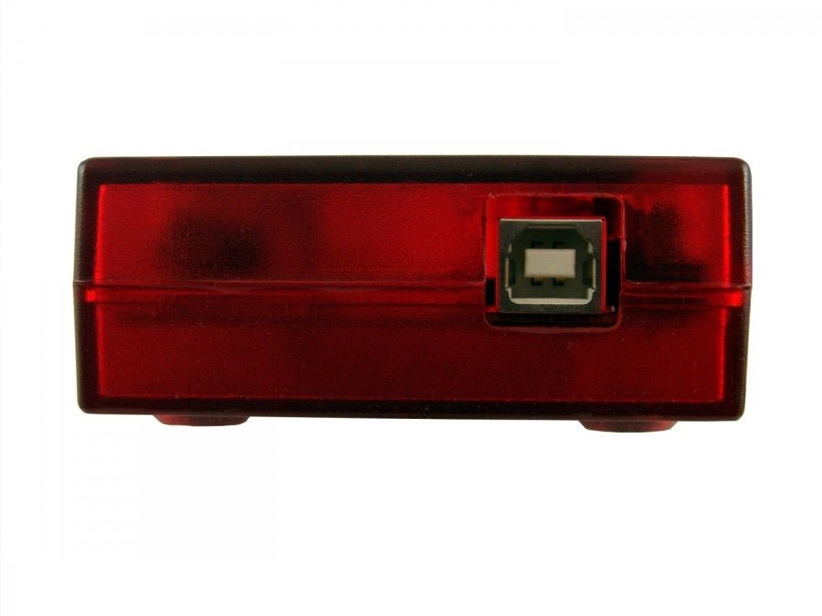
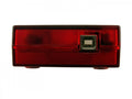
- Communication Edge: Has a USB type B connector.
- Screw Terminal Edge: Convenient connections for 4 analog inputs, both analog outputs, 4 flexible digital I/O (FIO), and both current sources. The screw terminals are arranged in blocks of 4, with each block consisting of Vs, GND, and two I/O. Also on this edge are two LEDs. One simply indicates power, while the other serves as a status indicator.
- DB Edge: Has 2 D-sub type connectors: a DB37 and DB15. The DB37 has some digital I/O and all the analog I/O. The DB15 has 12 additional digital I/O (3 are duplicates of DB37 I/O).

USB: All power and communication is handled by the USB interface.
LEDs: The Power and Status LEDs convey different information about the device.
GND/SGND: All GND terminals are the same. SGND has a self-resetting thermal fuse in series with GND.
VS: All VS terminals are the same. These are outputs that can be used to source about 5 volts.
10UA/200UA: Fixed current sources providing 10µA/200µA at a max voltage of about 3 volts.
AIN#: AIN0-AIN13 are the 14 analog inputs.
DAC#: DAC0 & DAC1 are the 2 analog outputs. Each DAC can be set to a voltage between about 0.02 and 5 volts with 12-bits of resolution.
FIO#/EIO#/CIO#/MIO#: These are the 20 digital I/O, and are also referred to as DIO0-DIO19. Besides basic digital I/O operations, some of these terminals can also be configured as Timers & Counters (frequency input, PWM output, etc.), SPI serial, I2C serial, and Asynchronous serial.
For information about reading inputs, start in Section 3. For information about setting outputs, start with the Waveform Generation Application Note.

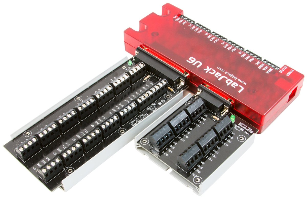
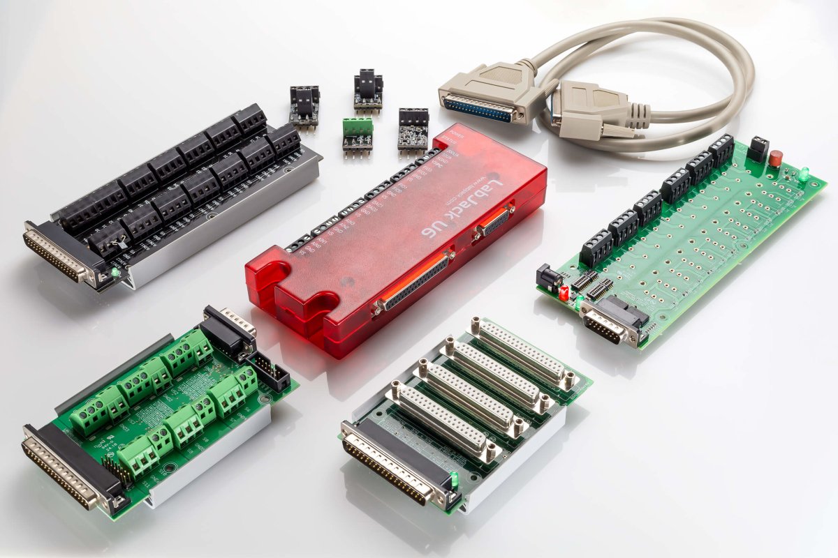
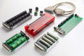
Optional Accessories:
The CB15 is a simple screw terminal breakout for the DB15 connector.
The CB37 is a simple screw terminal breakout board for the DB37 connector. It only works with the U6 and T7 devices and can also be paired with the Mux80 for high channel application up to 84 AINs.
The Mux80 is an Analog Input Expansion board for the T7 and U6. Connected directly to the DB37 connector is can allow a single device to read up to 84 AINs.
The RB12 Relay Board provides a convenient interface for the LabJack to industry standard relays to interface a LabJack with high voltages/currents. The RB12 relay board connects to the DB15 connector on the LabJack. Output or input
The LJTick-Divider (LJTD) signal-conditioning module is designed to divide 2 single-ended higher voltage analog signals down to 0-2.5 volt signals.
The LJTick-DAC (LJTDAC) provides a pair of 14-bit analog outputs with a range of ±10 volts. Plugs into any digital I/O block, and thus up to 10 of these can be used per device to add 20 analog outputs.
The LJTick-InAmp (LJTIA) signal-conditioning module provides two instrumentation amplifiers ideal for low-level signals such as bridge circuits (e.g. strain gauges) and thermocouples. Each amplifier converts a differential input to single-ended.
The LJTick-RelayDriver (LJTRD) allows 2 digital I/O lines to each control a relay or other moderate load up to 50V/200mA.
The LJTick-CurrentShunt (LJTCS) signal-conditioning module is designed to convert a 4-20 mA current loop input signal into a 0.47-2.36 volt signal.
The LJTick-Proto (LJTP) consists of an 8x8 grid of holes for prototyping custom signal-conditioning modules.
Support Resourses
LabJack Quickstart Tutorials
LabJack quickstart tutorials show new users how to measure a voltage, change a digital I/O, and set the voltage of an analog output using our free software. These tutorials teaches basic software and device functionality, and is also useful as a quick debugging check to verify that I/O on the device are working properly.
Returns & Exchanges
Return Policy
Everything LabJack sells has a 60-day money-back guarantee and 5-year warranty. Put LabJack to the test. Evaluate our hardware, software, documentation, customer service and support. You can request a full refund if you are not satisfied with a product for any reason. Refund requests are initiated from the Return Material Authorization (RMA) Page
*Please Note
LabJack does not resell any returned products. Don't worry, we also don't discard used LabJacks. Returns are earmarked for donations to STEM students and student led engineering teams.
Exchanges
Product exchanges are treated as returns and a new purchase. Return your unwanted device for a refund, and place a new order for the device or devices that better suit your needs.
U6 Datasheet and Application Notes
Visit the Support page for additional information.
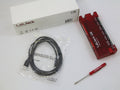
U6 Getting Started
 |
Install Software1. Download and install the U6's installation package. |
 |
Connect U62. Connect the U6 to the computer via USB.The U6's status LED should blink at power up and then stay solid on. If Windows asks about installing new hardware accept the defaults. |
 |
Run LJControlPanel3. LJControlPanel is a free application installed by the U6's installation package. You should be able to find it in the Start Menu links. |
U6's Quickstart4. See the U6's Quickstart page for more detailed instructions. |
New to Data Acquisition (DAQ)? Not Sure Where to Start?
Our engineers in Colorado, USA, provide real-time live chat. Click the chat bar at the bottom right of any page, or see our Contact page for other ways to get in touch with us.
Example Code/Wrappers: UD Library
UD= U3, U6, UE9
| Examples In... | Windows | Mac | Linux |
| DAQFactory | ✔ | ||
| LabVIEW | ✔ | ||
| C,C++, VC6 | ✔ | ||
| C, C++ | ✔ | ✔ | |
| Python | ✔ | ✔ | ✔ |
| MATLAB | ✔ | ||
|
Visual Basic (VB6, VBA) |
✔ | ||
|
Agilent VEE |
✔ | ||
| .Net (C#, VB) | ✔ | ||
| Java | ✔ | ||
| Delphi | ✔ | ||
| Igor Pro | ✔ | ||
| Pure Basic | ✔ | ||
| LabWindows/CVI | ✔ | ||
| DASYLab | ✔ |
U6 Product FAQs
LabJack Quickstart Tutorials
LabJack quickstart tutorials show new users how to measure a voltage, change a digital I/O, and set the voltage of an analog output using our free software. These tutorials teaches basic software and device functionality, and is also useful as a quick debugging check to verify that I/O on the device are working properly.
Detailed Comparison of the Different LabJack Devices
U3 compared to U12
The U3 is newer than the U12, and in general is faster, more flexible, and less expensive.
The U3 is about half the size of the U12. The enclosure can be mounted using a couple screws or DIN rail, whereas the U12 enclosure has no mounting options.
Command/response functions on the U3 are typically 5-20 times faster than on the U12. See Section 3.1 of the U3 User's Guide compared to the U12 data rates page.
The U3 has up to 16 analog inputs compared to 8 on the U12. Any channel can be measured differentially versus any other channel. Accuracy specs are better than the U12.
The U3-LV has single-ended ranges of 0-2.4 or 0-3.6 volts, and a differential range of ±2.4 volts (pseudobipolar only). The U3-HV has 12 flexible I/O capable of those same low-voltage ranges, and 4 high-voltage analog inputs with a range of ±10 volts or -10/+20 volts. The U12 has a ±10 volt single-ended input range, and differential input ranges varying from ±20 volts to ±1 volt (all true bipolar). The circuitry used by the U12 to provide those high bipolar ranges is simple and inexpensive, but has drawbacks including relativity poor input impedance and errors which are different on every channel. There are many devices on the market now that have copied the same circuitry from the U12 and have the same drawbacks.
The U3 supports input streaming with a max rate of up to 50 ksamples/second, compared to 1.2 ksamples/second for the U12. The U3 achieves the full 12-bit resolution up to 2.5 ksamples/second, and then as speed increases the effective resolution drops to about 10 bits due to noise.
The U3 has 2 10-bit DACs as does the U12. The DACs on the U3 are derived from a regulated voltage, whereas the U12 DACs are derived from the power supply, so the U3 DACs will be more stable.
The digital I/O on the U3 use 3.3 volt logic, and are 5 volt tolerant. The U12 has 5 volt logic.
The U3 can have up to 2 timers and 2 counters. The timers have various functionality including period timing, duty cycle timing, quadrature input, pulse counting, or PWM output. The U12 has 1 counter and no timers.
The U3 has master support for SPI, I2C, and asynchronous serial protocols. The U12 does not support I2C, but does have some SPI and asynchronous support.
The U3 is supported on Windows, Linux and Mac OS X. The U12 has full support for Windows, limited support for Linux, and limited public support for the Mac.
On Windows, the U3 uses the flexible UD driver which also works with the U6 & UE9. There is a specific separate driver for the U12.
The U3 is compatible with the LJTick signal conditioning modules, whereas the U12 is not. Current ticks include:
- LJTick-Divider (LJTD): Divides 2 single-ended higher voltage analog signals down to 0-2.5 volt signals. Install different resistors for different gain and offset.
- LJTick-DAC (LJTDAC): Provides a pair of 14-bit analog outputs with a range of ±10 volts. Plugs into any digital I/O block, and thus up to 10 of these can be used per U3/UE9 to add 20 analog outputs.
- LJTick-InAmp (LJTIA): Provides two instrumentation amplifiers ideal for low-level signals such as bridge circuits (e.g. strain gauges) and thermocouples. Each amplifier converts a differential input to single-ended.
- LJTick-RelayDriver (LJTRD): Allows 2 digital I/O lines on a U3/UE9 to each control a relay or other moderate load up to 50V/200mA.
- LJTick-CurrentShunt (LJTCS): Converts a 4-20 mA current loop input signal into a 0.47-2.36 volt signal.
- LJTick-Proto (LJTP): Consists of an 8x8 grid of holes for prototyping custom signal-conditioning ticks.
... versus UE9: (EOL)
The UE9 has all the same improvements as the U3 above, with the following additions and differences:
The UE9 is about twice the size of the U3.
The biggest difference is that the UE9 supports Ethernet communication in addition to USB. Ethernet communication uses standard TCP or UDP protocol, and supports Modbus/TCP. Ethernet speeds in command/response or stream mode are generally similar to USB speeds (see Sections 3.1 and 3.2 of the User's Guide for more information). The addition of an 802.11 WiFi bridge allows for inexpensive wireless data acquisition and control.
When using Ethernet only (not USB), the UE9 has at least 500 volts of electrical isolation.
The UE9 has 14 analog inputs and 2 analog outputs. The analog inputs and outputs on the UE9 have better accuracy, resolution, and linearity. The analog inputs are single-ended only, but the LJTick-InAmp can be used for low-level differential signals.
Each analog input can be configured individually as unipolar (four ranges from 0-5 volts to 0-0.625 volts) or true bipolar (±5 volts). Analog input resolution is 12-bits at max speed (12 us conversion time), increasing up to 16-bits at slower speeds (2.7 ms conversion time).
Maximum input stream rates range from 250 samples/second at 16-bit resolution to 50+ ksamples/second at 12-bit resolution. The UE9 has a very large 4 Mbit buffer for stream data, compared to a very small buffer on the U3.
The UE9 has up to 6 timers available compared to 2 on the U3.
The UE9-Pro has all the features of the normal UE9 with the addition of an auxiliary low-speed hi-resolution (24-bit) sigma-delta ADC. This converter takes about 125 ms per sample and provides an effective resolution of about 20-bits (18-bits noise free) over the 0-5 or ±5 volt ranges. Linearity and accuracy are also improved compared to the normal converter (which is still available on the UE9-Pro).
... versus U6:
The U6 is similar to a UE9 without Ethernet, but the U6 is newer and has some analog input improvements. Some key details:
USB only.
Up to 4 timers available.
20 digital I/O (compared to 23 on the UE9).
The U6/U6-Pro analog inputs have higher resolution than the UE9/UE9-Pro in most cases.
Analog inputs are single-ended or differential, with input ranges of ±10, ±1, and ±0.1 volts.
2 Fixed Current Outputs (200/10 μA).
... versus T7:
The T7 is similar to a U6 and UE9, but the T7 combines the benefits of both devices, namely the high quality analog of the U6 with the advantages of Ethernet that you get from the UE9. The T7-Pro extends the advantages even further by adding WiFi.
Other improvements over the U6 and UE9 include:
Supported by our 3rd generation cross platform LJM library.
Straightforward low-level interface that uses Modbus TCP registers to access all device functionality.
Compatibility with most SCADA Modbus TCP enabled systems for both wired and wireless operation.
12 digital I/O lines can be configured for various timing/counting functionality, which we now refer to as DIO extended features. Read more in the DIO EF section of the T-series datasheet.
23 digital I/O, up from 20 on the U6.
The analog input extended feature system (AIN-EF) has the ability to do math and processing in hardware. Calculations for things like average, RMS, and thermocouples can be done on the device.
Write Lua scripts that run on the device with or without a host computer.
Improved slot-style screw mounts on the enclosure, which makes it possible to wall mount the T7 in any orientation, and still have the ability to quickly 'un-hook' it from the screws.
... versus T4:
The T4 is a blend of a U3-HV and T7. It has the form factor and I/O of the U3-HV, analog specifications very similar to the U3-HV (e.g. 12-bit analog inputs), but it has the processor of the T7 resulting in various changes compared to the U3:
- Like all T-series devices, the T4 has Ethernet in addition to USB.
- Add a standard WiFi bridge for inexpensive wireless data acquisition and control.
- Supported by our 3rd generation cross platform LJM library.
- Straightforward low-level interface that uses Modbus TCP registers to access all device functionality.
- Compatibility with most SCADA Modbus TCP enabled systems for both wired and wireless operation.
- 10 digital I/O lines can be configured for various timing/counting functionality, which we now refer to as DIO extended features. Read more in the DIO EF section of the T-series datasheet.
- The analog input extended feature system (AIN-EF) has the ability to do math and processing in hardware. Calculations for things like average and RMS can be done on the device.
- Write Lua scripts that run on the device with or without a host computer.
- The T4 has 4 single-ended analog inputs with +/-10V range, plus up to 8 digital I/O lines can be configured as single-ended analog inputs with 0-2.5V range. Similar but not exactly the same as the U3 AIN system.
U6 vs U6-Pro
The U6-Pro has the following additional features:
- Low-Speed and High-Resolution (24-bit) sigma-delta ADC giving access to resolution indices 9 through 12.
Can LabJack be used for Industrial Applications?
LabJack Devices:
- Can comfortably operate within the industrial temperature range (-40°C to 85C)
- Are capable of being mounted via DIN Rail/LJ-Snap2d
- Integrate with Voltage Dividers for 24+ Volt signals
- NEMA 3 (or greater) enclosures recommended for any outdoor or indoor applications with dust, debris or in condensing humidity environments
- All LabJack products are covered by our industry leading 5 year warranty
- Have OEM Versions available for custom and embedded applications.
- Drawings and CAD Models Provided
- LabJack products are very robust, but subject to the influence of user connections.
- LabJack is not liable for any losses, expenses or damages beyond the LabJack device itself. See our Limitation of Liability for more details.

What Can I Do with a LabJack?
Read the output of sensors which measure voltage, current, power, temperature, humidity, wind speed, force, pressure, strain, acceleration, RPM, light intensity, sound intensity, gas concentration, position, and many more. A LabJack brings this data into a PC where it can be stored and processed as desired.
Control things like motors, lights, solenoids, relays, valves, and more.
Why LabJack?
Legendary Support
- Email responses that actually answer your question.
- Free lifetime support includes (some) engineering design help.
- The engineers who made the product also respond to your questions.
- Should your LabJack misbehave, we offer free RMA diagnostics & repairs.
Flexibility
- Software integrates easily. We don't force you into a certain software, programming environment or operating system.
- LabVIEW, C++, MATLAB, Python, Java, .NET, Delphi, Visual Basic, VB6, VBA, and more examples
- Linux, macOS, Windows
- Add new kinds of sensors on-the-fly. We provide inexpensive signal conditioning modules.
- Control valves, motors, lights, pumps, etc - using one of many digital I/O control options.
- Incorporate LabJack DAQ hardware using our OEM options.
Solutions over Show
- Our engineers speak directly.
- Just the information you need to make an informed choice.
- No marketing fluff, no empty promises
- Fair prices, nothing hidden, no extended warranties, no salesmen, no haggling, no pressure.
- We are an independent small business in Colorado who only answers to YOU our customer

What Type of Sensors Can I Connect to LabJack?
LabJack hardware can be connected to nearly any analog or digital sensor. Of course some sensors are easier than others to connect. If you haven't yet purchased your sensors please check out our App Notes for detailed guides and best practices. Generally the best sensors output an analog voltage in the 0-10v DC range. We have many signal conditioning modules we refer to as "Ticks" that make it easy to accept other signals and ranges
- LJTick-Current Shunt for 4-20mA signals
- LJTick-Divider for voltages over 10v
- LJTick-Vref for sensors that require a stable excitation/power source
- LJTick-Resistance for RTDs, Thermistors or resistive sensors
- LJTikc-InAmp for amplifying tiny signals like bridge circuits or thermocouples
What is the meaning of Data Acquisition?
DAQ is short for data acquisition which is short for data acquisition and control. The term describes the process of acquiring readings from sensors and transducers (temperature, pressure, strain, etc.), and controlling actuators (relays, solenoids, etc.). In our case the emphasis is on computer-based DAQ, where the LabJack is the interface that allows a computer to read from sensors and control actuators.
DAQ Definition: What Is A DAQ System?
DAQ is short for data acquisition which is short for data acquisition and control. The term describes the process of acquiring readings from sensors and transducers (temperature, pressure, strain, etc.), and controlling actuators (relays, solenoids, etc.). In our case the emphasis is on computer-based DAQ, where the LabJack is the interface that allows a computer to read from sensors and control actuators.
What is an analog input? (AI, AIN, ADC)
AI or AIN = Analog Input
ADC = Analog to Digital Converter
An analog input converts a voltage level into a digital value that can be stored and processed in a computer. Why would you want to measure voltages? There are a multitude of sensors available which convert things like temperature, pressure, etc. into voltages. The voltages can then be easily measured by various kinds of hardware, such as a LabJack U3-HV, and then read into a computer. The computer can then convert the voltage value into it's original type (temperature, pressure, etc) and the value can then be stored in a file, emailed to someone, or used to control something else outside of the computer.
Example:

Get temperature from a sensor using an analog input.
- Wire the output of the analog temperature sensor to a U3-HV as shown.
- Read the voltage on the computer to know the current temperature.
- This particular sensor outputs 0.01 volts per °F, so 0.76V corresponds with 76°F.
Explore LabJack's Analog Input App Note
How Can I Get a Free LabJack Shirt or Hat?
LabJack offers a variety of hats, shirts and other "merch" for our raving fans and supporters who will wear it with pride. Request one by entering a comment with your next order or email us and ask nicely.
U6 Craftsmanship
Exceptional price and performance

Easily Expandable
High Channel Count? Expand up to 84 Analog Inputs with affordable accessories
Explore morePowerful Digital I/O Capabilities
20 Digital I/O, Supporting SPI, I2C & More, PWM Outputs, Frequency Inputs, Counters, Timers and many more Extended Features
Explore more14 Analog Inputs
Analog input ranges: ±10V, ±1V, ±0.1V and ±0.01V 16-bit high-speed ADC (up to 100k samples/s)
Explore moreTemperature Sensor
The LabJack U6 has a temperature sensor located very close to the AIN0-AIN3 screw-terminals. Accuracy is ±2 degrees C (max). This sensor is particularly useful for thermocouple cold junction compensation (CJC).
Explore moreUSB Connection to Your Computer
The U6 has a full-speed USB 2.0 connection compatible with USB version 1.1 or later. This connection provides communication and power (Vusb). USB ground is connected to the U6 ground (GND), and USB ground is generally the same as the ground of the PC chassis and AC mains.
Explore more