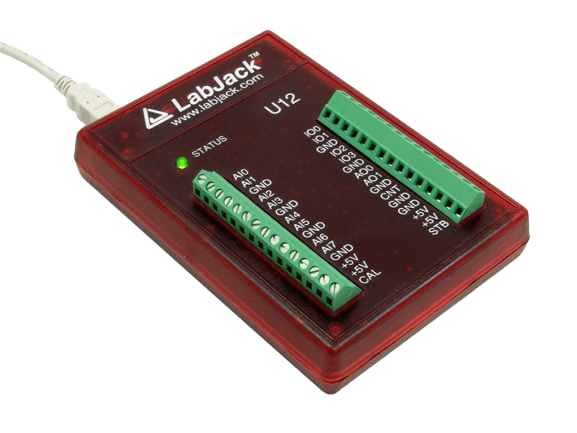


LabJack U12
USB DAQ device with 8 analog inputs(12-bit), 2 analog outputs(10-bit), 20 digital I/O, and a 32-bit counter.
USB Multifunction DAQ
The U12 is the original LabJack. The device is solid - the firmware hasn't changed in a decade, and it has a very long service record of reliability and customer satisfaction - all with an attractive price point. It can be used for measurement and control within simple analog and digital systems.
We continue to produce the U12 to support our customers who have integrated it into existing designs. For all new applications, we recommend the T4 or any of our other T-Series devices. This newer family offers faster speeds, greater hardware flexibility, and is supported by our latest cross-platform LJM API.
Stock status: In Stock
Stock status: In Stock
Stock status: In Stock
The Original LabJack

Product Specs
LabJack U12 Technical Specs
Technical Specifications
- 8 Single-Ended, 4 Differential 12-Bit Analog Inputs
- ±10 Volt Analog Input Range
- PGA with Gains of 1, 2, 4, 5, 8, 10, 16, or 20 V/V
- Up to 8 ksamples/Sec (Burst) or 1.2 ksamples/Second (Stream)
- Supports Software or Hardware Timed Acquisition
- 2 Analog Outputs
- 20 Digital I/O (Up to 50 Hz per I/O)
- 32-Bit Counter
- Watchdog Timer Function
- USB 2.0/1.1 Low Speed Interface (Data Rate Information)
- Connect Up to 80 LabJacks to One USB Host
- Complete Software Control, No Jumpers or Switches
- No Power Supply Needed
- Includes Sample Applications and Drivers
- Includes LabVIEW VIs
- Works with Windows 98SE, ME, 2000, XP, or Vista
- Includes Cable and Screwdriver
- Money Back Guarantee
- Approximately 4" x 6" x 1"
- Rated for Industrial Temperature Range
- OEM Board-Only Versions Available
- Complete specifications in Appendix A of User's Guide
For more technical specifications look at the U12's datasheet.
U12 Product Highlights
Analog Inputs:
The LabJack U12 has 8 screw terminals for analog input signals (AI0-AI7). These can be configured individually as 8 single-ended channels, 4 differential channels, or combinations in between. Each input has a ±10 volt input range, 12-bit resolution, and an input bias current of ±90 microamps. Differential channels can make use of the low noise precision PGA to provide gains up to 20.
The LabJack U12 is capable of both software and hardware timed acquisition. When using software timed acquisition (also called command/response), the PC sends a command to the LabJack, and it responds with data. This mode can acquire 4 channels at up to 50 samples/second per channel, or 8 channels at up to 25 samples/second per channel. When using hardware timed acquisition, the PC sends a command to the LabJack telling it to start a burst or stream mode acquisition. Both burst and stream mode take advantage of the LabJack's precision timing crystal and high-speed sample buffer. In burst mode, up to 4,096 samples will be acquired from 1-4 channels at up to 8,192 samples/second and stored in the buffer. After the acquisition is complete, the data is transferred to the PC. A hardware trigger can be configured for burst mode that starts the acquisition when a digital input changes state. In stream mode, data is acquired from 1-4 channels at up to 1,200 samples/second and stored in the LabJack buffer. Simultaneously, the data is transferred from the LabJack buffer to the PC buffer, allowing the data to be streamed to disk continuously. Click here for more info on data rates.
Analog Outputs:
The LabJack U12 has 2 screw terminals for analog output signals (AO0 & AO1). Each analog output can be set to a voltage between 0 and the supply voltage (+5 volts nominal) with 10-bits of resolution. The analog outputs are controlled in command/response mode at up to 50 Hz per channel.
Digital I/O:
The LabJack U12 has 20 digital I/O channels which can be individually configured as input or output.
Connections to 4 of the digital I/O are made with the built-in screw terminals (IO0-IO3). These 4 channels have built-in overvoltage/short-circuit protection. As inputs or outputs, they are controlled/read in command/response mode at up to 50 Hz per bit. As inputs only, they can be read with the high-speed burst and stream modes.
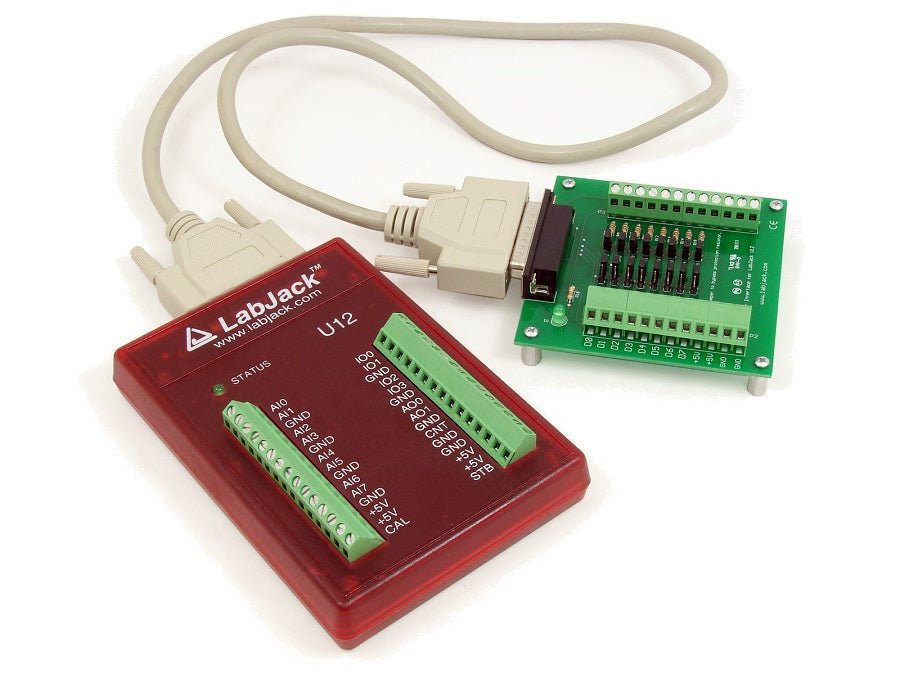
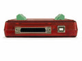
The remaining 16 digital I/O are accessed through the DB-25 connector and controlled/read in command/response mode at up to 50 Hz per bit. These channels can sink or source up to 25 mA each (total sink or source current of 200 mA max for all 16), allowing direct interface to many relays.
Counter:
There is one 32-bit counter available on the LabJack U12 (screw terminal CNT), capable of counting frequencies up to 1 MHz. The counter is read in command/response mode at up to 50 Hz or up to 300 Hz in hardware timed stream mode.
Watchdog Timer Function for Unattended Operation:
The LabJack U12 also has a watchdog timer function available which can change the states of digital I/O if the LabJack does not successfully communicate with the PC within a specified timeout period. This function could be used to reboot the PC allowing for reliable unattended operation.
Portable Data Acquisition and Control:
When used with a notebook PC, the LabJack U12 becomes a convenient portable data acquisition and control system. The watchdog timer function allows the development of a system which has the reliability of a datalogger with the power of a PC. The low-power design of the LabJack U12 allows it to draw all it's power from the USB port. Also, no UPS is needed when using a LabJack U12 with a notebook PC. In the event of power loss, both the LabJack and the notebook will continue to operate.
High Channel Count Applications:
By using USB hubs, up to 80 LabJacks can be connected to a single USB host, providing an inexpensive solution for low-speed high channel count applications.
Other Highlights
Free Example Application Software:
Includes various example applications, including LJlogger and LJscope. LJlogger provides datalogger type functionality. It reads all inputs, controls all outputs, writes real time data to disk, and sends email when events are triggered. LJscope is a simple virtual oscilloscope program. This software is free and can be downloaded from the U12 Library page for evaluation.
Free Driver Software:
Drivers are provided as a DLL which can be called from most programming languages. Also included are an ActiveX wrapper and LabVIEW VIs which call all the functions in the DLL. Most driver functions have a demo input, so applications can be developed and tested without hardware.
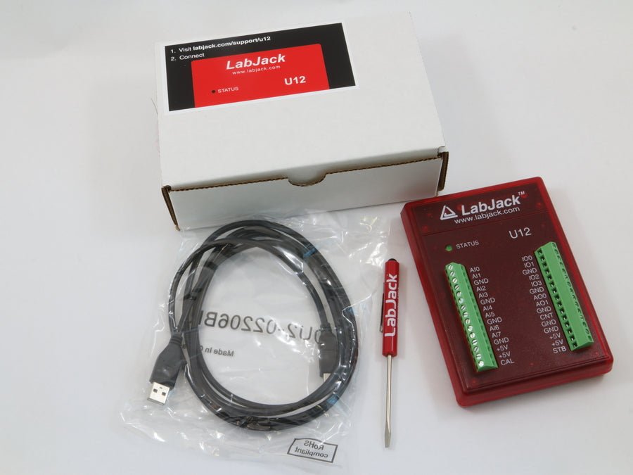
Includes Everything for Out-of-the-Box Operation:
Everything needed (software, screwdriver, and USB cable) is included with the LabJack U12. Installation is very simple and takes just a few minutes:
- Connect to the USB port on a PC running Windows 98SE/ME/2000/XP/Vista/7/8 using the included cable. The low-level drivers, which come with Windows, will be installed automatically.
- Run the LabJack installation program to install the high-level drivers and example applications.
Optional Accessories
The LabJack U12 comes complete, but we do offer a few optional accessories.
The CB25 provides screw-terminal connections and short-circuit/overvoltage protection for the 16 I/O which are accessed through the DB25 connector.
The RB16 provides sockets for industry standard miniature I/O modules (solid state relays).
The EI-1022 is an inexpensive and easy to use temperature probe.
The EI-1040 is a single-supply dual instrumentation amp that provides high impedance and high gain.
Satisfaction Guaranteed
Everything we sell has a 30-day money back guarantee. If, for any reason, you are not satisfied with a product, contact us to arrange your choice of a refund or replacement. In addition, the LabJack U12 is covered by a 1-year limited warranty.
Technical Support
All LabJacks include lifetime technical support. Support resources include forum, FAQs, email, and telephone.
Drivers and Examples:
The U12 Quickstart page describes software options. LabJack provides drivers for the three major operating systems, and examples for most common programming languages.
U12 Package Contents
Package Contents (Non-OEM)
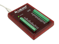
- U12 unit itself in red enclosure
- USB cable (6 ft / 1.8 m)
- Screwdriver
- Other package details: No software CD included. Download the software from labjack.com.
- Retail packing (Package) size: 8" x 5.5" x 2"
- Retail packing (Package) wt: 1 lb
Product Variations
U12 Product Variations
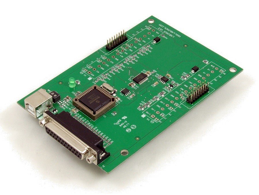
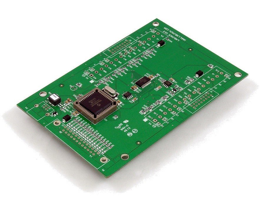
OEM Versions (U12-PH and U12-NTH)
There are 2 OEM board-only versions of the U12 available for customers interested in designing the U12 into another product.
LabJack U12-PH (OEM Version): This -PH board has pin-headers installed (component side) instead of screw-terminals, and the LED is mounted on the component side.

LabJack U12-NTH (OEM Version): This -NTH board does not have any through-hole components installed (screw-terminals, pin-headers, LED, USB connector, and DB25 connector).

The OEM versions do not include anything besides the board itself. Dimensional drawings and software are available on the U12 Appendix B Page.
Support Resources
U12-Helpful Links
LabJack U12 Hardware Overview
The Original LabJack
USB to Your PC
USB Port for Easy Connectivity to Your PC, USB Also provides 5v to Power the LabJack and some sensors
Explore more8 Analog Inputs
The LabJack U12 has 8 screw terminals for analog input signals. These can be configured individually and on-the-fly as 8 single-ended channels, 4 differential channels, or combinations in between. Each input has a 12-bit resolution and an input bias current of ±90 µA.
Explore moreDigital I/O Lines
20 Digital I/O Lines, Connections to 4 of the LabJack’s 20 digital I/O are made at the screw terminals, and are referred to as IO0-IO3. Each pin can individually be set to input, output high, or output low.
Explore more2 Analog Output Lines-AO0 & AO1
The LabJack U12 has 2 screw terminals for analog output voltages. Each analog output can be set to a voltage between 0 and the supply voltage (+5 volts nominal) with 10-bits of resolution.
Explore moreDB25 Allows for Expansion
The DB25 connector provides connections for 16 digital I/O lines, called D0-D15. It also has connections for ground and +5 volts.
Explore more